 |
CIS-E Vacuum system |
 |
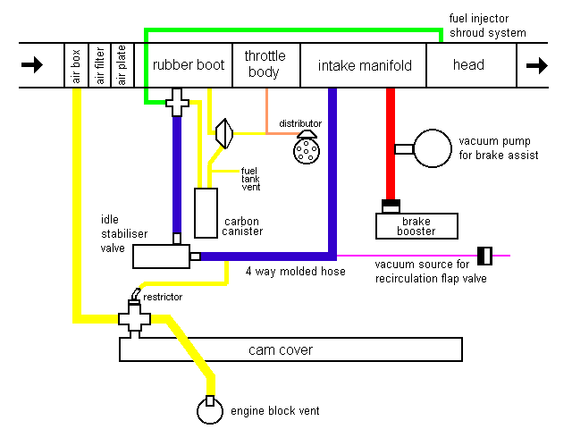
This is how the various components of the 1984-87 Coupe and 4000 vacuum systems are connected. Line thickness represents approximate hose type. The thickest are molded rubber or plastic. The connection to the throttle body is ahead of the butterflies.
Color codes:
red = brake power assist system
yellow = emissions systems - PCV and fuel tank vapor recovery
blue = idle management
green = fuel injector "air shrouding" system
orange = distributor advance
purple = AC only systems

Explanation of functions:
| |
Power brakes - I dunno how it works but it seems to be set up to grab vacuum wherever and whenever there is any available. |
| |
Emissions systems - draws crankcase fumes into the intake air ahead of the sensor plate under load, at idle (closed throttle) it cheats and draws it, without letting the sensor know, into the intake manifold. There is also the fuel tank vent system, coupled with the charcoal canister. I'm still trying to figure out which direction the air flows in some of these hoses, and when... |
| |
The idle, warm or cold, is adjusted by the computer using the idle stabilizer valve, whenever the idle switch on the throttle body is closed. It works by rapidly opening and closing as needed, from its rest position which is partly open. |
| |
The fuel injector "air shrouding" system is, I think, designed to help cool the injectors to reduce the problem of vapor lock (this occurs when too much heat soaks into the injectors, after a hot shut down, and causes some fuel to turn to vapor, which prevents the fule system from applying proper pressure to the injectors in order to open them). I believe this system simply draws a small amount of air that has reached the intake manifold back through the throttle body, forcing it to travel via some carefully designed cavities around the injector body (between the tip and main seals). |
| |
The distributor advance is pretty simple (!), advance is determined by the pressure drop relative to atmospheric just ahead of the throttle body butterflies. This seems to be at its greatest when the throttle is just opened a little bit.
In the middle of this hose there is a little vacuum actuated switch with a screwdriver adjustable center (not shown). I always thought this was some mysteriously important bit of gear. Now I know it's just a sender for the upshift light control unit. |
| |
The AC line shown is used to store vacuum, through a one way valve, in a canister (three tennis balls) under the left fender, and when the heater control is moved all the way to the "cold" position an electrical valve uses this vacuum to close the recirculating flap. |
I have not shown the vacuum supply for the differential locks on the quattro models, but it is similar in location and function to the recirculation flap system, although I do not think it has a storage system since it only functions when the car is in motion.
|