 |
Instrument Cluster |
 |
Since I had to mess with the clock in my 1989 90 Quattro one more time, I thought it would be nice to document the process of removing and eviscerating the instrument cluster for those who might be foolish enough to follow in my footsteps...
tools required -
removing cluster -
dismantling -
removing clock -
testing clock
You will need the following tools:
- 10 mm wrench (usually) to disconnect battery
- 24 mm socket and driver for steering wheel nut
- medium phillips head screwdriver for wheel cover and cluster
- small flat screwdriver to aid harness removal and for tach/clock removal
- 7 mm socket and driver to remove gauge nuts
You also might find it handy to have available:
- clean, well lit work space
- dielectric grease for all connections
- soldering iron, solder, and wicking braid for repairing circuit board
- 6 to 12 volt DC power supply to test clock
- spare cluster light bulbs to replace duds
tools required (top) -
removing cluster -
dismantling -
removing clock -
testing clock
First you need to remove the instrument cluster. As with any project that even remotely involves the cars electrical system, you should disconnect the battery ground connection (and take precautions to safeguard your radio memory).
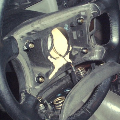
| Pull the horn button off with mild violence. There are snap things holding each of the four corners. This is best done with the plastic parts warm to minimise breakage. (The parts that break are still available at the dealer.)
Gently pull the horn wire of its post in the button pad, and set the pad aside.
|  |
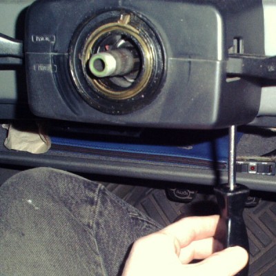
| After letting the steering wheel lock click into place and determining how to orient the wheel when replacing, use the 24 mm socket to remove the wheel nut. Set the nut, washer, and wheel aside. | 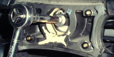 |
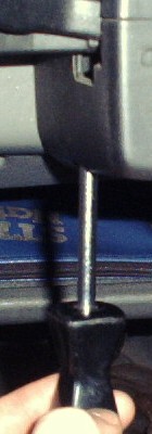
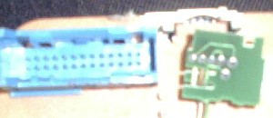
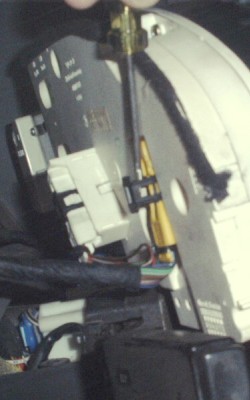 | This part is a little tricky. You use a small flat bladed screwdriver to pop up the black plastic clips in the center of these plugs.
Once the clips are released like this, the plug comes out easily - in fact they will probably come right out in the same motion as your "popping up" effort.
On this cluster there are three such clips, yellow and white ones on the left, and a blue one on the right. The yellow and blue ones should be on all cars. The white one runs the On Board Computer - the thing that makes the big orange "OK" when you start the car. There may also be another, smaller one for the trip computer (I had previously removed mine).
The color coding is nice, since you do not have to mark them to remember where to reinstall them. |
The instrument cluster is now no longer attached to the car and may be brought inside to your well lit work area for surgery. Be sure to lay the harnesses and their plugs out so they do not fall in to the depths of the dashboard...
tools required (top) -
removing cluster -
dismantling -
removing clock -
testing clock
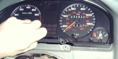
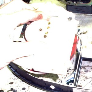
Here is the cluster (a little too brightly lit!)lying face down with the top towards us for ease of access:
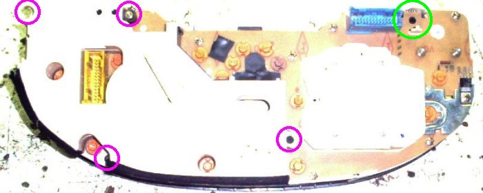
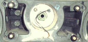
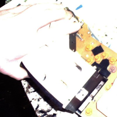
| First remove the On Board Computer/Trip Computer module.
The four screws circled in purple in the photo above hold it to the back of the assembly. Once they are removed, the assembly can be gently pulled off.
If the car has a trip computer, there will be a set of wires going to the top right (green circle) with a little thing that reads the fuel gauge (below). Carefully unsnap it from its plastic mount.
|  |
To remove the main circuit board (gently!), you will undo the fasteners circled in this next photo. The ones circled in green are just straightforward phillips head screws, although they have hex heads also. The one circled in yellow is the same, except that it also holds down the voltage regulator (for the coolant and fuel gauges) and its heat sink - it should also have a washer. Circled in red are the nuts holding the connections to the gauges to the board, which should also have washers.
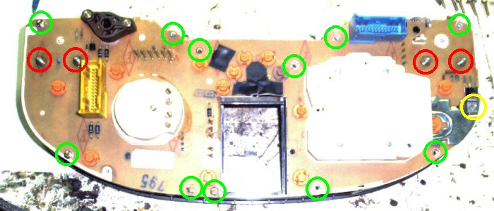
| Once these are all removed, the circuit board can be slowly, carefully pulled up off the assembly. The pins which carry signals to the main gauges will slide out of their sockets. Take some care in that upper right area (where the Trip Computer fuel input was attached) since the board is held down by a small spur on one of the plastic moldings. | 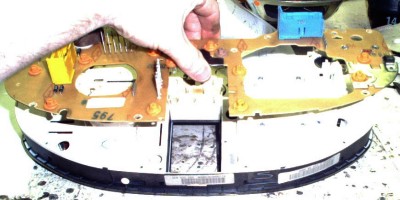 |
 | The main tachometer and speedometer subunits can now be gently lifted out of the housing and bezel. | 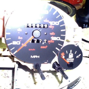 |
Be careful with the tachometer subunit (on the left in this veiw) since the instrument light dimmer control shaft and its spring are not really held by anything other than the subunit and the circuit board.
tools required (top) -
removing cluster -
dismantling -
removing clock -
testing clock
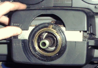
| To actually replace the clock, you will first need to remove the tachometer from its subunit. There are five closely spaced slotted screws on the back of the round raised area of the back of this subunit. The ones circled in red hold the tach in place. Once they are removed it can be slid gently up off the plastic base - there is a felt washer around the clock setting shaft which may need to be coaxed over the fatter part of the shaft in order for everything to come apart neatly. | 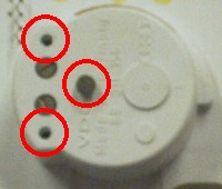 |
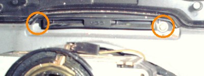
| Now that the clock is exposed, from the front you can see two small slotted screws, where the blue circles are. Undo them and remove the clock. Replace with your new clock, or a known good used one. | 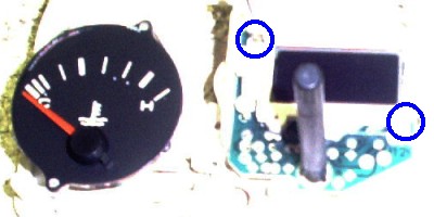 |
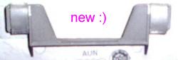
The time adjustment shaft pulls off the clock unit with a little gentle effort - you will need to swap over if you use a new clock.
I tried to use a new clock... but the one I ordered is not exactly the same as my bad one or my "maybe good" one. It would require a little too much surgery to graft into my car, so I will investigate further and if I find a good part number I will list it here.
tools required (top) -
removing cluster -
dismantling -
removing clock -
testing clock
If you wish to test your clock here is how to do it. The clock has two pins sticking out the rear. The one to the inboard, ie closer to the middle of the instrument cluster, is the ground and the other one is the positive connection. You can use a 12 volt supply, but the clock will operate on 6 or 9 volts just fine.
Note: The clock lighting is independent of the clock itself - it is just one of those many, many lights snapped into the circuit board.
| Hook up your power supply, as shown in this remarkably bad photograph, and see if the clock still exhibits whatever failure mode that caused you to remove it. If not, examine the main circuit board carefully for problems with solder joints where the clock connects and fix them if you find any. If the clock is still bad, replace it. Mine had a problem with the LCD display in the tens of minutes position. | 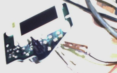 |
tools required (top) -
removing cluster -
dismantling -
removing clock -
testing clock
|